
- All
- Product Name
- Product Keyword
- Product Model
- Product Summary
- Product Description
- Multi Field Search
Views: 0 Author: Site Editor Publish Time: 2026-07-15 Origin: Site


Specifying the wrong mechanical unit doesn’t just reduce operational efficiency. It introduces premature wear and drastically increases thermal failure risks. Ultimately, poor component selection drives up lifecycle maintenance efforts. Moving from general machine design to finalizing a transmission gearbox requires a major engineering shift. You must transition from theoretical power requirements into real-world operational constraints. A simple horsepower mismatch can easily bring an entire production line to a halt.
This guide breaks down standard engineering frameworks used across the industry. We evaluate, shortlist, and select a reliable unit safely. You will explore how to align available options against your performance, spatial, and budgetary baseline. By following these steps, you will learn actionable methods to prevent common sizing mistakes. These practical principles guarantee lasting mechanical reliability.
Selection must begin with exact load characteristics, not just target horsepower.
Matching the gearbox type (e.g., planetary vs. worm) requires accepting specific trade-offs between efficiency, backlash, and footprint.
Ignoring the Service Factor (SF) or thermal ratings is the leading cause of field failures.
System-level optimization requires treating the motor and gearbox as a single integrated combination.
You must establish a concrete mathematical foundation before comparing physical components. Do not guess the required forces. Exact operational physics dictate every subsequent decision.
Identify the continuous running torque first. Next, define the peak or starting torque required to move the load initially. Starting a heavy stationary mass requires significantly more force than maintaining its motion. Engineers often undersize components by calculating only the running torque. You must measure dynamic acceleration forces accurately. Undersizing leads directly to broken gear teeth during startup phases.
Establish the exact gear ratio needed for your system. This calculation reduces standard motor speed down to the required machine speed. You find the ratio by dividing the motor input RPM by your desired output RPM. Accuracy here prevents downstream speed mismatches. Always account for slight efficiency losses during power transfer.
Map out the daily operating hours carefully. Count the exact frequency of starts, stops, and rotational reversals. A system running continuously operates under entirely different thermal conditions than one cycling briefly. High-frequency start-stop cycles introduce severe stress on internal bearings. You must categorize your application as continuous, intermittent, or highly dynamic.
Define the available physical envelope surrounding your machine. Note the required shaft orientation clearly. You may need inline, right-angle, or parallel shaft configurations. Confirm specific mounting configurations early during the design phase. Parallel shaft designs often save valuable radial space. Right-angle designs help fit drives into tight corners.
Follow these numbered steps to lock in your baseline metrics:
Measure the exact mass and friction coefficient of your load.
Define the desired acceleration time required for your process.
Calculate the absolute peak torque using fundamental physics formulas.
Determine the continuous running torque to sustain motion.
Select the proper shaft orientation based on available machine space.
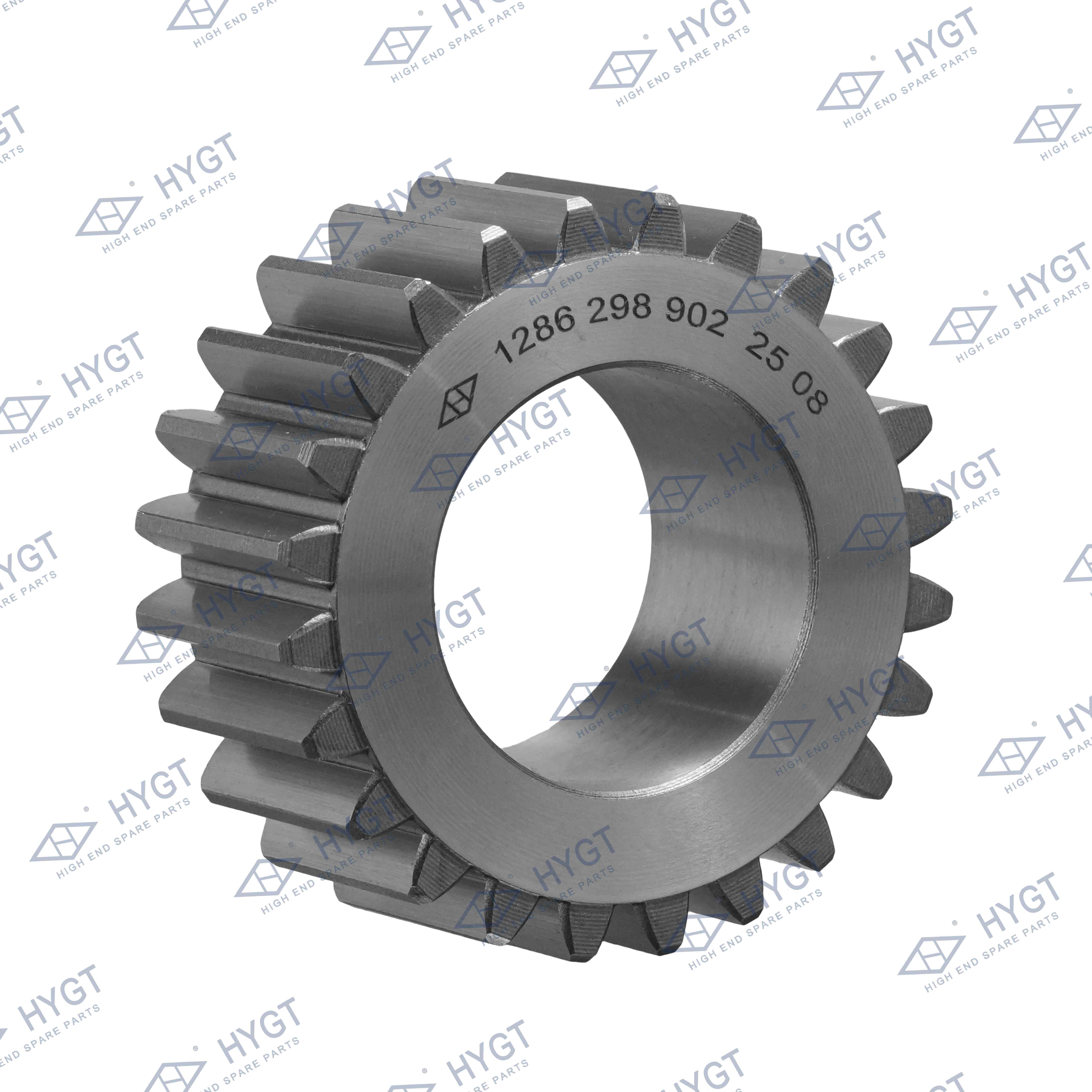
Once you define the baseline metrics, compare core Gearbox types. Each internal gear design handles power delivery differently. We must accept specific trade-offs regarding efficiency, footprint, and backlash.
Planetary designs offer extreme torque density. They provide a highly compact physical footprint. They feature remarkably low backlash. This makes them ideal for precision servo applications like robotics. Multiple planet gears share the load simultaneously. This load distribution handles high shock levels efficiently. However, planetary units typically carry a higher initial investment.
Helical gears deliver excellent mechanical efficiency. The angled teeth engage gradually, providing exceptionally quiet continuous operation. Engineers favor them for high-power industrial applications. They dominate standard transmission gearbox requirements in continuous-duty manufacturing. While slightly larger than planetary units, they offer unmatched durability for heavy loads.
Worm gear reducers provide a highly cost-effective solution. They naturally create a right-angle shaft orientation. These units are often self-locking, preventing the load from back-driving. However, they remain inherently less efficient. The sliding friction between the worm and the wheel generates significant heat. You must account for this efficiency loss during motor sizing.
Bevel designs offer highly efficient right-angle power transmission. You generally choose them when intersecting shafts are mandatory. They avoid the steep efficiency loss associated with sliding worm gears. Bevel units transfer power smoothly and handle high torque applications effortlessly.
Gearbox Type | Relative Efficiency | Backlash Level | Best Application Scenario |
|---|---|---|---|
Planetary | High (90-95%) | Very Low | Precision servo control, robotics |
Helical | Very High (95-98%) | Moderate | Continuous industrial conveyors |
Worm | Low to Moderate (50-85%) | High | Cost-sensitive right-angle setups |
Bevel | High (90-95%) | Moderate | Efficient right-angle transmission |
Calculating raw torque is never enough. You must adjust the theoretical physics to match harsh operational realities. This step ensures long-term mechanical survival.
A Service Factor (SF) serves as a numerical multiplier. It typically ranges from 1.0 to 3.0. You apply it directly to the base torque requirement. This multiplier accounts for the inevitable stresses of industrial environments. An SF of 1.0 implies perfectly uniform operation under ideal conditions. Real-world applications rarely meet this ideal standard.
You must adjust the SF based on your load uniformity. Different machines experience vastly different stress profiles. Examine the driven equipment closely.
Uniform Loads: Agitators mixing pure liquids or lightweight fans. These often use an SF around 1.0 to 1.2.
Moderate Shocks: Multi-cylinder pumps, industrial ovens, or heavy conveyors. These require an SF around 1.25 to 1.5.
Heavy Shocks: Rock crushers, punch presses, or vibrating screens. These demand an SF of 2.0 or higher.
Increase the multiplier for machines running around the clock. Compare a 24/7 facility to a shop running intermittent eight-hour shifts. Continuous operation prevents the oil from cooling down fully. It also accelerates metal fatigue cycles. Extended run times demand a higher Service Factor to ensure component survival.
Undersizing guarantees premature failure. A low SF leads directly to stripped gears and burned bearings. Oversizing presents its own problems. An excessive SF adds unnecessary weight, expands the footprint, and consumes excess capital. Balance remains crucial. Always follow authoritative manufacturer tables to pinpoint the exact multiplier.
Best Practice: Always err on the side of a slightly higher Service Factor if your load parameters fluctuate unpredictably. A 10% safety margin prevents catastrophic downtime.
Selecting an excellent reducer means nothing if it rejects the motor. You must integrate these two components seamlessly. System harmony determines final output performance.
Ensure the reflected load inertia at the motor shaft remains within an acceptable ratio. Compare it directly to the motor’s own internal rotor inertia. This concept becomes absolutely critical for dynamic servo applications. High mismatch ratios cause tuning instability. The motor will struggle to control the load predictably. Target an inertia ratio under 10:1 for highly dynamic systems.
Verify all physical connection points rigorously. Check flange dimensions against motor specifications. Measure shaft diameters precisely to ensure coupling compatibility. NEMA (National Electrical Manufacturers Association) and IEC (International Electrotechnical Commission) standards provide excellent baseline compatibility. However, proprietary servo mounts require exact geometric matching. A slight misalignment will destroy input bearings rapidly.
Evaluate combined mechanical efficiency thoroughly. Do not evaluate a single transmission gearbox in isolation. The motor and reducer function as an integrated combination. A 90% efficient reducer paired with an 85% efficient motor yields a combined system efficiency of only 76.5%. Treat them as a unified energy transfer system. This holistic approach prevents unexpected power shortages at the machine level.
Check these critical integration points before purchasing components:
Confirm pilot diameter tolerances on both mating flanges.
Ensure the motor shaft length prevents bottoming out inside the reducer.
Verify keyway dimensions align perfectly for secure torque transmission.
Check the bolt circle diameter for accurate face-mounting.
Even the strongest gears fail in the wrong environment. You must protect the internal components from external threats. Environmental analysis prevents premature degradation.
Mechanical power limits often exceed thermal limits significantly. The gears might easily transmit the required torque physically. However, the friction heat might boil the internal oil. Ensure the unit dissipates heat effectively in your target operating environment. High ambient temperatures degrade lubrication rapidly. You may need to specify secondary cooling loops or external fans to prevent thermal overload.
Evaluate sealing options strictly based on your facility. Will the machine operate in highly dusty environments? IP65 ratings handle standard dust and low-pressure water. Hygienic food and beverage environments demand strict washdown capabilities. These settings require IP69K ratings to survive high-temperature, high-pressure chemical sprays. Specify stainless steel housings where corrosion poses a daily threat.
Determine available maintenance access early. Does the application allow for scheduled oil changes? Some installations sit high in the ceiling or inside enclosed cages. Inaccessibility makes standard fluid changes impossible. In these scenarios, a sealed-for-life synthetic grease solution becomes mandatory. Synthetic lubricants typically handle wider temperature ranges and extend maintenance intervals effectively.
Ensure your final selections meet relevant engineering guidelines. Use AGMA (American Gear Manufacturers Association) standards to verify load capacities. You can also reference ISO standards for metric applications in specific global industries. Following authoritative frameworks ensures proven reliability. Manufacturer testing according to these standards provides confidence in published torque ratings.
Selecting the ideal power transmission solution requires careful technical balancing. You must weigh torque density against overall efficiency. You must balance environmental resilience against spatial constraints. Every application demands a unique, calculated compromise among these critical variables.
Take these concrete next steps to finalize your integration effectively:
Finalize your machine drawings using the exact verified load requirements.
Consult directly alongside a trusted manufacturer to review your calculations.
Verify thermal limits match your expected ambient environment perfectly.
Confirm supplier lead times before finalizing your official bill of materials.
A: Divide the input speed (motor RPM) by your desired output speed (machine RPM). The resulting numerical ratio inversely multiplies your motor's output torque. Always remember to subtract known efficiency losses from the final calculated output torque.
A: Mechanical rating defines the maximum physical torque the internal gears can handle safely. Thermal rating dictates the maximum continuous power the unit can transmit without overheating internal oil and seals. Always specify your system based strictly on the lower of these two ratings.
A: Integrated gearmotors reduce the physical footprint significantly. They eliminate coupling misalignment issues and simplify the purchasing process. Separate components offer far greater maintenance flexibility. They allow you to replace just a failed motor without discarding the entire functioning transmission system.


