
- All
- Product Name
- Product Keyword
- Product Model
- Product Summary
- Product Description
- Multi Field Search
Views: 0 Author: Site Editor Publish Time: 2026-07-14 Origin: Site


Selecting a mechanical drive involves high operational stakes. You cannot just match torque and speed figures. You must balance mechanical efficiency, lifecycle longevity, and tight spatial constraints. When you misalign a drive type against its specific application, you invite mechanical trouble. This mismatch causes premature internal wear. It leads directly to severe thermal inefficiencies and frustrating, unplanned downtime. Such failures halt entire production lines and waste valuable engineering resources. This guide breaks down the core drive configurations you will encounter. We will examine their inherent engineering trade-offs objectively. You will learn how to evaluate these mechanical units for highly specific industrial applications. We will explore the vital parameters needed for accurate specification. You will discover how thermal limits often dictate continuous operating conditions. Ultimately, this engineering knowledge helps you specify the correct mechanical solution for any demanding operational environment.
Helical gearboxes deliver high efficiency and heavy-duty performance but require adequate installation space.
Planetary gearboxes offer superior torque density and precision (low backlash) in compact footprints, though at a higher initial cost.
Worm gearboxes provide high reduction ratios and self-locking capabilities economically, but suffer from lower mechanical efficiency due to sliding friction.
Bevel gearboxes are the standard for right-angle power transmission, requiring precise alignment for optimal longevity.
Selection must prioritize continuous operating conditions, thermal ratings, and maintenance accessibility over baseline purchase price.
The powertrain represents a critical point of failure in any facility. If you over-specify a unit, you waste valuable resources on unnecessary capacity. If you under-specify the unit, you accelerate mechanical breakdown rapidly. You must establish firm baseline requirements before exploring specific mechanical categories. Gather exact data on input speed and desired output speed. You must calculate accurate torque parameters and document the operating duty cycle. You also need to understand your prime mover characteristics completely.
Operators must look through an operational efficiency lens. Long-term energy consumption matters immensely. Consider the physical maintenance demands over a 10-to-15-year lifecycle. High mechanical efficiency saves massive amounts of energy over a decade. A less efficient unit consumes more electricity every single hour. You must prioritize operational longevity and energy conservation above all other metrics.
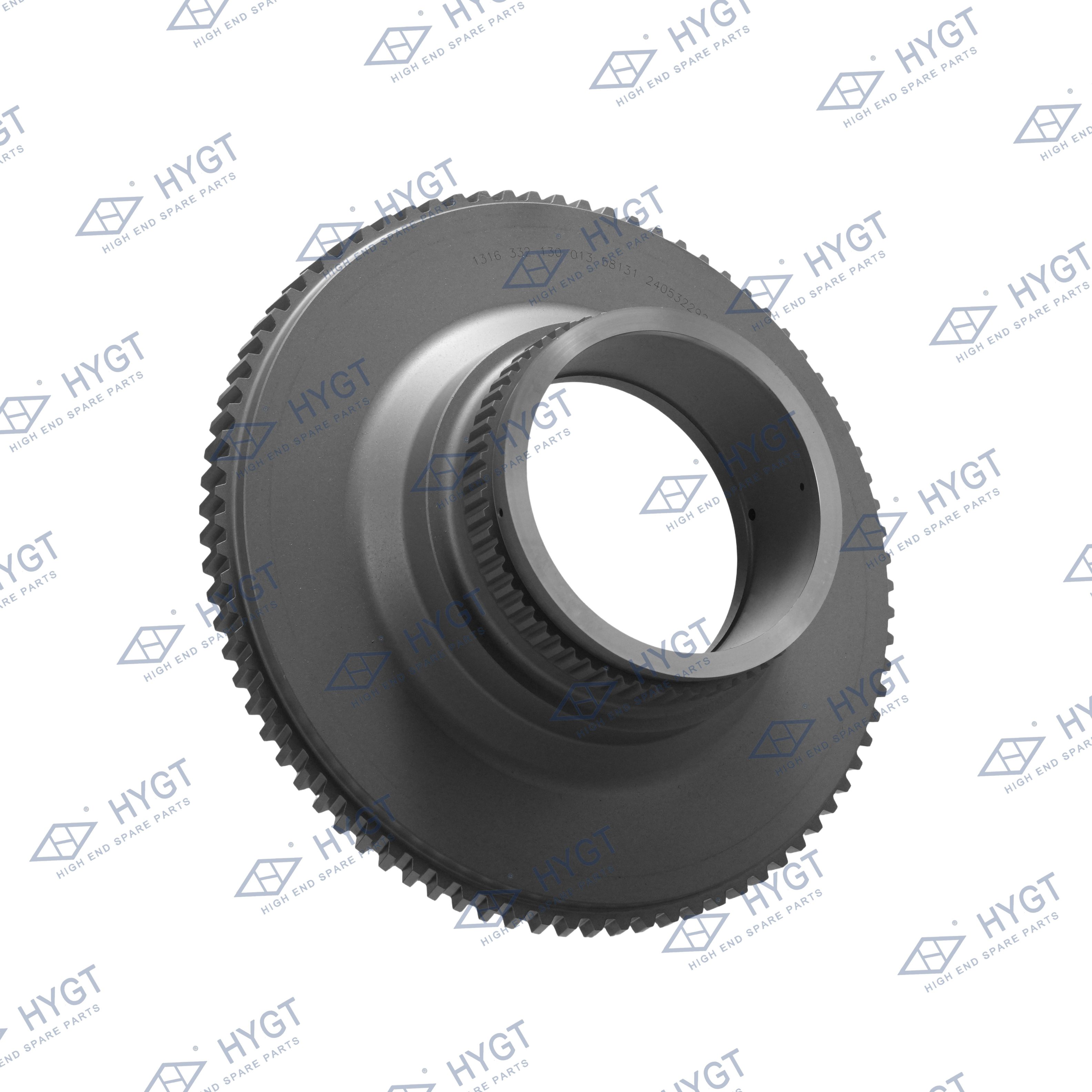
Every mechanical advantage comes attached to a specific engineering trade-off. We must maintain an objective view of these systems. There is no perfect universal solution. You must match the mechanism to the exact application profile.
Angled teeth define this mechanism. These angled teeth engage gradually during operation. This gradual engagement allows for smooth, remarkably quiet power transmission. The load transfers seamlessly from one tooth to the next. This creates a highly stable internal environment.
They deliver phenomenal efficiency, often exceeding 95 percent. They handle exceptionally high loads easily. They remain highly durable under continuous operation. Many heavy industries rely on this exact Gearbox design for their main conveyor lines. The parallel shaft alignment simplifies power transfer over long distances.
However, the angled teeth generate significant axial thrust. The gears constantly push away from each other along the shaft. You must install robust thrust bearings to counteract this lateral force. They also generally require a larger physical footprint than planetary alternatives. You need ample installation space to accommodate their housing.
Monitor thrust bearing temperatures regularly.
Verify shaft alignment during initial installation.
Use vibration analysis to detect early gear pitting.
A planetary configuration uses a central sun gear. This sun gear drives multiple planet gears simultaneously. These planet gears orbit inside a stationary outer ring gear. This brilliant design distributes the operational load evenly across multiple contact points.
They provide exceptional torque density in a highly compact footprint. Coaxial shaft alignment simplifies machinery layout significantly. The input and output shafts share the exact same axis. They offer very low backlash. This makes them absolutely ideal for servo motors and precision applications. Robotics rely heavily on this configuration.
The trade-offs involve high internal complexity. They are much more difficult to service in the field. Their extremely compact size makes them sensitive to thermal limits. Heat cannot escape easily from the small housings. Continuous high-speed operation often requires external cooling mechanisms.
Ignoring thermal duty cycles during specification.
Attempting field repairs without specialized alignment tools.
Pairing them with highly unstable prime movers.
A threaded worm screw meshes into a toothed worm wheel. This interaction occurs at a strict 90-degree angle. Engineers typically machine the worm from hardened steel and the wheel from softer bronze. The bronze acts as a sacrificial wear element.
They offer massive reduction ratios within a single stage. You can achieve a 60:1 reduction easily. The right-angle design remains highly compact for tight spaces. They run inherently quietly due to the sliding action. Many models feature self-locking capabilities. This prevents back-driving during power failures, which is vital for hoists and lifts.
The mesh relies heavily on sliding friction rather than rolling friction. This sliding action causes significant efficiency loss. They typically operate at 50 to 80 percent efficiency. This sliding friction also generates substantial heat during operation. You lose a large portion of motor power to thermal energy.
Cone-shaped gears transmit power across intersecting shafts. These shafts typically sit at exact 90-degree angles. Configurations include straight, spiral, and hypoid designs. Spiral bevels feature curved teeth for smoother engagement. Hypoid designs allow the shafts to cross without intersecting directly.
They provide highly efficient right-angle power transmission. They perform much better than worm drives in terms of energy conservation. Spiral bevel designs handle extreme shock loads exceptionally well. They are standard in heavy mobile equipment and large industrial mixers.
You must execute highly precise mounting and alignment. Poor alignment destroys bevel gears rapidly. The contact pattern must remain perfectly centered on the teeth. Straight bevels often become quite noisy at higher operating speeds. They vibrate more than spiral variations.
You must evaluate multiple integration dimensions before making a final selection. A well-integrated industrial gearbox operates seamlessly for years. A poorly specified unit causes constant headaches.
Compare the lifecycle energy usage carefully. High-efficiency models like helical and planetary designs waste very little power. Worm drives experience inherent energy loss through heat. Over thousands of operating hours, a 20 percent efficiency drop consumes vast amounts of electricity. You must calculate the kilowatt-hours lost over a decade of continuous operation.
Efficiency Comparison Chart
Configuration Type | Typical Mechanical Efficiency | Primary Source of Energy Loss |
|---|---|---|
Helical (Single Stage) | 95% - 98% | Rolling friction, oil churning |
Planetary | 90% - 97% | Multiple mesh points, seal drag |
Spiral Bevel | 94% - 97% | Rolling friction, bearing drag |
Worm (High Ratio) | 50% - 75% | Heavy sliding friction |
Evaluate machine footprint realities strictly. Inline configurations suit long, narrow spaces perfectly. Parallel shaft designs work well when shafts sit side-by-side. Right-angle units fit neatly into tight corners. You cannot force an inline planetary unit into a space designed for a right-angle worm drive. Measure the available envelope before specifying any components.
Application requirements dictate necessary precision levels. Backlash refers to the slight play between mating gear teeth. Standard material handling tolerates moderate backlash. Conveyor belts do not need micro-millimeter positional accuracy. However, robotics and CNC machining demand physical perfection. In these environments, planetary low-backlash units are absolutely mandatory. Any play in the gears ruins the final machined product.
Always verify strict adherence to industry standards. Look for AGMA (American Gear Manufacturers Association) ratings on the nameplate. ISO standards also verify load capacities and thermal limits. These certifications ensure the unit performs exactly as advertised. Never trust unverified performance claims. Certified load curves guarantee the unit will survive your specific application parameters.
Even the finest engineering fails without proper maintenance. You must understand the physical realities of operating heavy machinery. Environmental factors play a massive role in equipment longevity.
Thermal ratings often limit continuous operation long before mechanical ratings do. A unit might handle the physical torque load easily but overheat quickly. The internal oil acts as a heat sink. If the oil degrades, temperatures spike. You must address cooling requirements properly. Some applications require external cooling fans or heat exchangers. Others rely on high-grade synthetic lubricants to dissipate heat faster than mineral oils.
Premature failure rarely originates in the gear teeth themselves. Seal failures and lubricant breakdown cause most catastrophic breakdowns. When a seal fails, oil leaks out. Simultaneously, dirt and moisture enter the housing. This contamination destroys bearings rapidly. You must maintain proper oil levels consistently.
Utilize the exact oil viscosity recommended by the manufacturer.
Install high-quality desiccant breathers to block airborne moisture.
Sample the oil quarterly to check for microscopic metal wear particles.
Replace shaft seals at the first sign of external weeping.
Never ignore radial and axial forces. Belts, pulleys, and heavy chains apply immense lateral pressure to the shafts. These external forces translate directly to the internal bearings. This lateral pressure is called an Overhung Load. If you exceed the published OHL ratings, you will destroy the shaft bearings rapidly. Heavy shock loads from rock crushers or shredders require highly elevated service factors. You must account for starting, stopping, and sudden jams.
Follow a systematic approach to narrow down your options. Skipping steps leads directly to specification errors.
Document the exact load type accurately. Classify it as a uniform load, moderate shock, or heavy shock application. This classification determines the correct service factor. A uniform load might use a 1.0 service factor. A heavy shock load requires a 2.0 or higher service factor. This multiplier increases the required physical size of the unit.
Filter out incompatible types based on spatial limits. Eliminate units that do not match your required shaft orientations. If you need a right-angle drop-in, eliminate all inline planetary options immediately. Focus only on configurations that physically fit your machinery envelope.
Use a standardized formula to calculate energy consumption. Compare the kilowatt-hours used by a highly efficient helical unit versus a worm drive. Calculate the energy savings generated over a 24-month continuous operation period. The immense energy savings of the helical unit often justify switching away from older worm technologies.
Vet manufacturers thoroughly based on engineering support. Check their availability of replacement parts in your specific region. Demand transparent publication of exact torque and thermal curves. A reliable vendor provides comprehensive engineering data without hesitation. They should offer application engineers to review your calculations.
The "best" industrial powertrain component remains strictly application-dependent. You must match the mechanism to the specific physical task.
High mechanical efficiency pays massive dividends in long-term energy savings. Do not ignore the power lost to heat and friction.
Thermal limits often dictate operational success. Keep units cool and well-lubricated to ensure maximum lifecycle longevity.
Always account for Overhung Loads and severe shock loads during the specification phase. Protect the internal bearings at all costs.
Take immediate action by compiling your motor data, duty cycle requirements, and dimensional constraints into a single specification sheet. Gather your environmental operating temperatures as well. Once you have this foundational data, engage directly with engineering or application support teams. Let them validate your selection calculations. Their expertise ensures optimal mechanical integration and prevents costly specification errors.
A: Yes, operators frequently make this specific replacement for energy efficiency upgrades. Helical-bevel units save massive amounts of electricity compared to worm drives. However, you must meticulously verify spatial dimensions first. You also need to confirm right-angle shaft drop-in compatibility. The mounting footprint usually differs between the two designs.
A: A service factor acts as a crucial safety multiplier. You apply this multiplier to the baseline motor power. It accounts for harsh operational realities like heavy shock loads, continuous 24/7 duty cycles, and frequent starting frequencies. A 1.5 service factor ensures the unit handles 50 percent more physical stress than the nominal baseline.
A: Longevity depends heavily on standard L10 bearing life ratings and strict adherence to maintenance schedules. If you operate the unit within its thermal limits and keep the oil perfectly clean, it lasts a long time. Well-maintained units typically achieve anywhere from 10,000 to over 50,000 operating hours before requiring a major overhaul.


